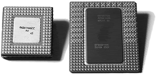
PGA Chip Packaging
Variations on the pin grid array (PGA) chip packaging have been the most commonly used chip packages over the years. They were used starting with the 286 processor in the 1980s and are still used today for Pentium and Pentium Pro processors.
PGA takes its name from the fact that the chip has a grid-like array of pins on the bottom of the package. PGA chips are inserted into sockets, which are often of a zero insertion force (ZIF) design. A ZIF socket has a lever to allow for easy installation and removal of the chip.
Most Pentium processors use a variation on the regular PGA called staggered pin grid array (SPGA), in which the pins are staggered on the underside of the chip rather than in standard rows and columns. This was done to move the pins closer together and decrease the overall size of the chip when a large number of pins is required.
Figure below shows a Pentium Pro that uses the dual-pattern SPGA (on the right) next to an older Pentium 66 that uses the regular PGA. Note that the right half of the Pentium Pro shown here has additional pins staggered among the other rows and columns.

Older PGA variations had the processor die mounted in a cavity underneath the substrate, with the top surface facing up if you turned the chip upside down. The die was then wire-bonded to the chip package with hundreds of tiny gold wires connecting the connections at the edge of the chip with the internal connections in the package.
After the wire bonding, the cavity was sealed with a metal cover. This was an expensive and time-consuming method of producing chips, so cheaper and more efficient packaging methods were designed. Most modern processors are built on a form of flip-chip pin grid array (FC-PGA) packaging.
This type still plugs into a PGA socket, but the package itself is dramatically simplified. With FC-PGA, the raw silicon die is mounted face down on the top of the chip substrate, and instead of wire bonding, the connections are made with tiny solder bumps around the perimeter of the die.
The edge is then sealed with a fillet of epoxy. With the original versions of FC-PGA, you could see the backside of the raw die sitting on the chip. Unfortunately, there were some problems with attaching the heatsink to an FC-PGA chip. The heatsink sat on the top of the die, which acted as a pedestal.
If you pressed down on one side of the heatsink excessively during the installation process (such as when you were attaching the clip), you risked cracking the silicon die and destroying the chip. This was especially a problem as heatsinks became larger and heavier and the force applied by the clip became greater.
AMD decreased the risk of damage by adding rubber spacers to each corner of the chip substrate, thus preventing the heatsink from tilting excessively during installation. Still, these bumpers could compress, and it was all too easy to crack the die.
The Athlon XP currently uses FC-PGA with spacers at each corner of the substrate, and some aftermarket vendors sell specially designed shims that help provide additional protection. The Athlon 64 uses a different heatsink design, which attaches the heatsink to a clip.
The clip is then screwed to the motherboard, which helps prevent damage to the processor. Intel revised its packaging with a newer FC-PGA2 version used in the newer Pentium III and all Pentium 4 processors.
This incorporates an integrated protective metal cap called a heat spreader that sits on top of the die, enabling larger and heavier heatsinks to be installed without any potential damage to the processor core. Ironically, the first processor for PCs to use a heat spreader was made by AMD (the K6 family).
Future packaging directions are headed toward what is called BBUL (bumpless build-up layer) packaging. This will embed the die completely in the package; in fact, the package layers will be built up around and on top of the die, fully encapsulating it within the package.
This will embed the chip die and allow for a full flat surface for attaching the heatsink, as well as shorter internal interconnections within the package.