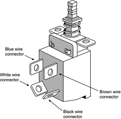
Power Switch Connectors
Three main types of power switches are used on PCs. They can be described as follows:
-
Integral Power Supply AC switch
-
Front Panel Power Supply AC switch
-
Front Panel Motherboard Controlled switch
The earliest systems had power switches integrated or built directly into the power supply, which turned the main AC power to the system on and off. This was a simple design, but because the power supply was mounted to the rear or side of the system, it required reaching around to the back to actuate the switch.
Also, switching the AC power directly meant the system couldn't be remotely started without special hardware. Starting in the late '80s, systems began using remote front panel switches. These were essentially the same power supply design as the first type.
The only difference was that the AC switch was now mounted remotely (usually on the front panel of the chassis), rather than integrated in the power supply unit. The switch was connected to the power supply via a four-wire cable, and the ends of the cable were fitted with spade connector lugs, which plugged onto the spade connectors on the power switch.
The cable from the power supply to the switch in the case contained four color-coded wires. In addition, a fifth wire supplying a ground connection to the case was sometimes included. The switch was usually included with the power supply and heavily shrink-wrapped or insulated where the connector lugs attached to prevent electric shock.
This solved the ergonomic problem of reaching the switch, but it still didn't enable remote or automated system power-up without special hardware. Plus, you now had a 120V AC switch mounted in the chassis, with wires carrying dangerous voltage through the system.
Some of these wires are hot anytime the system is plugged in (all are hot with the system turned on), creating a dangerous environment for the average person when messing around inside the system. The four or five wires are usually color-coded as follows:
-
Brown and blue. These wires are the live and neutral feed wires from the 120V power cord to the power supply. These are always hot when the power supply is plugged in.
-
Black and white. These wires carry the AC feed from the switch back to the power supply. These leads should be hot only when the power supply is plugged in and the switch is turned on.
-
Green or green with a yellow stripe. This is the ground lead. It should be connected to the PC case and should help ground the power supply to the case.
On the switch, the tabs for the leads are usually color-coded; if not, you'll find that most switches have two parallel tabs and two angled tabs. If no color-coding is on the switch, plug the blue and brown wires onto the tabs that are parallel to each other and the black and white wires to the tabs that are angled away from each other.
If none of the tabs are angled, simply make sure the blue and brown wires are plugged into the most closely spaced tabs on one side of the switch and the black and white wires on the most closely spaced tabs on the other side

As long as the blue and brown wires are on the one set of tabs and the black and white leads are on the other, the switch and supply will work properly.
If you incorrectly mix the leads, you will likely blow the circuit breaker for the wall socket because mixing them can create a direct short circuit.
All ATX and subsequent power supplies that employ the 20-pin motherboard connector use the PS_ON signal to power up the system.
As a result, the remote switch does not physically control the power supply's access to the 120V AC power, as in the older-style power supplies.
Instead, the power supply's on or off status is toggled by a PS_ON signal received on pin 14 of the ATX connector. The PS_ON signal can be generated physically by the computer's power switch or electronically by the operating system.
PS_ON is an active low signal, meaning that the power supply voltage outputs are disabled (the system is off) when the PS_ON is high (greater than or equal to 2.0V). This excludes the +5VSB (Standby) on pin 9, which is active whenever the power supply is connected to an AC power source.
The power supply maintains the PS_ON signal at either 3.3V or 5V. This signal is then routed through the motherboard to the remote switch on the front of the case. When the switch is pressed, the PS_ON signal is grounded. When the power supply sees the PS_ON signal drop to 0.8V or less, the power supply (and system) is turned on.
Thus, the remote switch in an ATX-style system (which includes NLX and SFX systems as well) carries up to only +5V of DC power, rather than the full 120V–240V AC current like that of the older AT/LPX form factors.