SCSI Cable and Connector Pinouts
Two electrically different versions of SCSI exist: single-ended and differential. These two versions are electrically incompatible and must not be interconnected; otherwise, damage will result. Fortunately, very few differential SCSI applications are available in the PC industry, so you will rarely (if ever) encounter one.
Within each electrical type (single-ended or differential), there are basically two SCSI cable types:
-
A cable (Standard 8-bit SCSI)
-
P cable (16-bit Wide SCSI)
The 50-pin A-cable is used in most SCSI-1 and SCSI-2 installations and is the most common cable you will encounter. SCSI-2 Wide (16-bit) applications use a P cable instead, which has 68 pins. You can intermix standard and Wide SCSI devices on a single SCSI bus by interconnecting A and P cables with special adapters.
SCSI-3 applications that are 32-bit wide would have used an additional Q cable, but this was finally dropped from the SCSI-3 standard after it was never implemented in actual products.
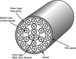
SCSI cables are specially shielded with the most important high-speed signals carried in the center of the cable and less important, slower ones in two additional layers around the perimeter. A typical SCSI cable is constructed as shown in Figure below.

This specialized construction is what makes SCSI cables so expensive, as well as thicker than other types of cables. Note this specialized construction is necessary only for external SCSI cables. Cables used to connect devices inside a shielded enclosure (such as inside a PC) can use much less expensive ribbon cables.
The A cables can have pin-header–type (internal) connectors or external shielded connectors, each with a different pinout. The P cables feature the same connector pinout on either internal or external cable connections.
Single-Ended SCSI Cables and Connectors
The single-ended electrical interface is the most popular type for PC systems. The A cable is available in both internal unshielded and external shielded configurations. A hyphen preceding a signal name indicates the signal is Active Low. The RESERVED lines have continuity from one end of the SCSI bus to the other.
In an A cable bus, the RESERVED lines should be left open in SCSI devices (but may be connected to ground) and are connected to ground in the bus terminator assemblies. In the P and Q cables, the RESERVED lines are left open in SCSI devices and the bus terminator assemblies.
IBM used the SCSI interface in virtually all PS/2 systems introduced after 1990. These systems use a Micro-Channel SCSI adapter or have the SCSI Host Adapter built in to the motherboard. In either case, IBM's SCSI interface uses a special 60-pin, mini-Centronics–type external shielded connector that is unique in the industry.
A special IBM cable is required to adapt this connector to the standard 50-pin Centronics-style connector used on most external SCSI devices. The pinout of the IBM 60-pin mini-Centronics–style external shielded connector.
The pin arrangement is unique, the pin-number–to–signal designations correspond with the standard unshielded internal pin header type of SCSI connector. IBM has discontinued this design in all its systems because after the PS/2 series, all have used conventional SCSI connectors.
High Voltage Differential SCSI Signals
High Voltage Differential SCSI is not normally used in a PC environment but is very popular with minicomputer installations because of the very long bus lengths that are allowed. This has changed with the introduction of Low Voltage Differential signaling for SCSI, bringing the benefits of differential signaling to lower-end and more mainstream SCSI products.
Differential signaling uses drivers on both the initiator and target ends of the bus and makes each signal work in a push/pull arrangement, rather than a signal/ground arrangement as with standard single-ended SCSI. This enables much greater cable lengths and eliminates some of the problems with termination.
Almost all PC peripherals produced since the beginning of SCSI have been SE types. These are incompatible with HVD devices, although HVD devices can be used on an SE bus with appropriate (and expensive) adapters. The LVD devices, on the other hand, can be used on an SE bus if they are multimode devices, in which case they switch into SE mode.
If all devices—including the host adapter—support LVD mode, all the devices switch into that mode and much longer cable lengths and higher speeds can be used. The normal limit for an SE SCSI bus is 1.53 meters maximum (about 5–10 feet) and up to 20MHz.
If run in LVD mode, the maximum bus length goes up to 12 meters (about 40 feet) and speeds can go up to 80MHz. HVD SCSI supports bus lengths of up to 25 meters (about 80 feet). Note that almost all modern SCSI hard disks are Ultra2 or Ultra3 devices, which means by default they are also LVD or multimode LVD/SE devices.
Expanders
SCSI expanders separate a SCSI bus into more than one physical segment, each of which can have the full SCSI cable length for that type of signaling. They provide a complete regeneration of the SCSI bus signals, allowing greater cable lengths and incompatible devices to essentially share the same bus.
An expander also can be used to separate incompatible parts of a SCSI bus—for example, to keep SE and HVD SCSI devices in separate domains. Expanders are transparent to the software and firmware on the bus, and they don't take up a device ID.
They are usually capable of providing termination if located at the end of a bus segment, or they can have termination disabled if they are in the middle of a bus segment.
Because of their expense, expanders are not normally used except in extreme situations in which no other alternative remains. In most cases, it is better to stick within the recommended cable and bus length requirements and keep incompatible devices, such as HVD devices, off a standard SE or LVD bus.
Termination
Because a SCSI bus carries high-speed electrical signals, it can be affected by electrical reflections that might occur within any transmission line system. A terminator is designed to minimize the potential for reflections or noise on the bus, as well as to create the proper load for the bus transmitter circuits.
Terminators are placed at each end of the bus to minimize these problems. Despite the simple rules that only two terminators must be on the bus and they must be at each end, I still see improper termination as the most common cause of problems in SCSI installations.
Several types of SCSI terminators are available, dependent on the bus signaling and speed requirements:
-
Passive
-
Active (also called Alternative 2)
-
Forced Perfect Termination (FPT): FPT-3, FPT-18, and FPT-27
-
HVD termination
-
LVD termination
The first three are used on single-ended SCSI buses only. Passive terminators use a passive network of 220-ohm and 330-ohm resistors to control bus termination. They should be used only in narrow (8-bit) SCSI buses running at 5MHz. Passive terminators allow signal fluctuations in relation to the terminator power signal on the bus.
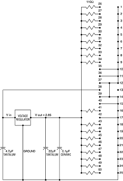
Usually, passive terminating resistors suffice over short distances, such as 2 or 3 feet, but for longer distances or higher speeds, active termination is a real advantage. Active termination is required with Fast SCSI. Figure below shows the schematic of a typical passive terminator.

Passive terminators can be plugged in to the unused SCSI port or be built in to many low-speed SCSI devices such as scanners, optical drives, and removable-media drives. On such devices, you can activate or deactivate built-in passive termination with jumper blocks, a toggle switch, or some other form of selector switch—depending on the device.
Active terminators use built-in voltage regulator ICs combined with 110-ohm resistors. An active terminator actually has one or more voltage regulators to produce the termination voltage, rather than resistor voltage dividers alone. This arrangement helps ensure that the SCSI signals always are terminated to the correct voltage level.
Active terminators often have some type of LED indicating the termination activity. The SCSI-2 specification recommends active termination on both ends of the bus and requires active termination whenever Fast or Wide SCSI devices are used.
Most high-performance host adapters have an "auto-termination" feature, so if it is the end of a chain, it terminates itself. Figure below shows a typical active terminator.

A variation on active termination is available for single-ended buses: forced perfect termination (FPT). Forced perfect termination is an even better form of active termination in which diode clamps are added to eliminate signal overshoot and undershoot.
The trick is that instead of clamping to +5 and ground, these terminators clamp to the output of two regulated voltages. This arrangement enables the clamping diodes to eliminate signal overshoot and undershoot, especially at higher signaling speeds and over longer distances.
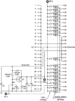
Forced perfect termination is technically not found in the SCSI specifications but is the superior type of termination for single-ended applications that experience high levels of electrical noise. Figure below shows the schematic of a typical FPT-18 type terminator (18 lines forced perfect, designed for 50-pin connections).

FPT terminators are available in several versions. FPT-3 and FPT-18 versions are available for 8-bit standard SCSI, whereas the FPT-27 is available for 16-bit (Wide) SCSI. The FPT-3 version forces perfect the three most highly active SCSI signals on the 8-bit SCSI bus, whereas the FPT-18 forces perfect all the SCSI signals on the 8-bit bus except grounds.
FPT-27 also forces perfect all the 16-bit Wide SCSI signals except grounds. HVD buses require HVD terminators, constructed using a passive network of 330-ohm/150-ohm/330-ohm resistors. The only choice is that the terminator matches your cable or device connection. The same is true for Low Voltage Differential buses.
They require LVD terminators for the bus to function properly. One twist is that special LVD/SE (active) multimode terminators are available. These function as LVD types on an LVD bus and as active types on an SE bus.
Note that if any SE devices are on the bus, it functions in SE mode and never uses LVD mode, severely limiting bus length and performance. If any SE-only terminators or SE devices are on the bus, the bus defaults into SE mode.
Special terminators also are required for LVD and HVD SCSI, so if you are using those interfaces, be sure your terminators are compatible. With LVD or HVD buses, you don't have much choice in terminator types, but for single-ended buses, you have at least three choices.