SCSI Cables and Connectors
The SCSI standards are very specific when it comes to cables and connectors. The most common connectors specified in this standard are the 50-position unshielded pin header connector for internal SCSI connections and the 50-position shielded Centronics latch-style connectors for external connections.
The shielded Centronics-style connector also is called Alternative 2 in the official specification. Passive or Active termination (Active is preferred) is specified for both single-ended and differential buses. The 50-conductor bus configuration is defined in the SCSI-2 standard as the A cable.
Older narrow (8-bit) SCSI adapters and external devices use a full-size Centronics-type connector. Figure below shows what the low-density, 50-pin SCSI connector looks like.

The SCSI-2 revision added a high-density, 50-position, D-shell connector option for the A-cable connectors. This connector now is called Alternative 1. Figure below shows the 50-pin, high-density SCSI connector.

The Alternative 2 Centronics latch-style connector remains unchanged from SCSI-1. A 68-conductor B-cable specification was added to the SCSI-2 standard to provide for 16- and 32-bit data transfers; the connector, however, had to be used in parallel with an A cable.
The industry did not widely accept the B-cable option, which has been dropped from the SCSI-3 standard. To replace the ill-fated B cable, a new 68-conductor P cable was developed as part of the SCSI-3 specification. Shielded and unshielded high-density D-shell connectors are specified for both the A and P cables.
The shielded high-density connectors use a squeeze-to-release latch rather than the wire latch used on the Centronics-style connectors. Active termination for single-ended buses is specified, providing a high level of signal integrity. Figure below shows the 68-pin, high-density SCSI connector.

Drive arrays normally use special SCSI drives with what is called an 80-pin Alternative-4 connector, which is capable of Wide SCSI and also includes power signals. Drives with the 80-pin connector are usually hot-swappable—they can be removed and installed with the power on—in drive arrays. The 80-pin Alt-4 connector is shown in below.

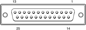
Apple and some other nonstandard implementations from other vendors used a 25-pin cable and connector for SCSI devices. They did this by eliminating most of the grounds from the cable, which unfortunately results in a noisy, error-prone connection.
These 25-pin connectors and cables are not compliant with any SCSI standard; you should avoid them if possible. The connector used in these cases was a standard female DB-25 connector, which looks exactly like a PC parallel port (printer) connector.
Unfortunately, you can damage equipment by plugging printers into DB-25 SCSI connectors or by plugging SCSI devices into DB-25 printer connectors. So, if you use this type of SCSI connection, be sure it is well marked because there is no way to tell DB-25 SCSI from DB-25 parallel printer connectors by looking at them. The nonstandard DB-25 SCSI connector is shown in below.

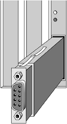
Again, I recommend avoiding making SCSI connections using this type of nonstandard cable or connector. Fibre Channel SCSI devices running at 200MBps can connect to various types of devices, depending on the gigabit interface connector (GBIC) module installed in the host adapter.
The module could use a subscriber connector (SC) for fiber-optic cable, a high-speed serial data connector (HSSDC) for copper cable, or a DB-9 connector for copper cable. The GBIC module can be removed from the host adapter, as shown in Figure below.

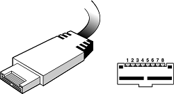
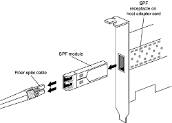
400MBps devices can connect to the HSSDC connector shown in Figure 8.10 if copper wire is used, or they can connect to the modular small form factor pluggable (SFP) connector shown in Figure below if fiber-optic cable is used.

Or they can connect to the modular small form factor pluggable (SFP) connector shown in Figure below if fiber-optic cable is used.
