SCSI Drive Configuration
SCSI drives are not too difficult to configure, but they are more complicated than ATA drives. The SCSI standard controls the way the drives must be set up. You need to set up two or three items when you configure a SCSI drive:
-
SCSI ID setting (0–7 or 0–15)
-
Terminating resistors
The SCSI ID setting is very simple. Up to 7 SCSI devices can be used on a single narrow SCSI bus or up to 15 devices on a wide SCSI bus, and each device must have a unique SCSI ID address. There are 8 or 16 addresses respectively, and the host adapter takes 1 address, so the rest are free for up to 7 or 15 SCSI peripherals.
Most SCSI host adapters are factory-set to ID 7 or 15, which is the highest priority ID. All other devices must have unique IDs that do not conflict with one another. Some host adapters boot only from a hard disk set to a specific ID. Older Adaptec host adapters required the boot hard disk to be ID 0; newer ones can boot from any ID.
Setting the ID usually involves changing jumpers on the drive. If the drive is installed in an external chassis, the chassis might have an ID selector switch that is accessible at the rear. This selector makes ID selection a simple matter of pressing a button or rotating a wheel until the desired ID number appears.
If no external selector is present, you must open the external device chassis and set the ID via the jumpers on the drive. Three jumpers are required to set the SCSI ID; the particular ID selected actually is derived from the binary representation of the jumpers themselves.
One example is setting all three ID jumpers to off, resulting in a binary number of 000b, which translates to an ID of 0. A binary setting of 001b equals ID 1, 010b equals 2, 011b equals 3, and so on. Unfortunately, the jumpers can appear either forward or backward on the drive, depending on how the manufacturer set them up.
SCSI termination is very simple. Termination is required at both ends of the bus; there are no exceptions. If the host adapter is at one end of the bus, it must have termination enabled.
If the host adapter is in the middle of the bus, and if both internal and external bus links are present, the host adapter must have its termination disabled and the devices at each end of the bus must have terminators installed. Unfortunately, the majority of problems I see with SCSI installations are the result of improper termination.
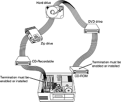
Figure below shows a representation of a SCSI bus with several devices attached. In this case, the host adapter is at one end of the bus and a CD-ROM drive is at the other. For the bus to work properly, those devices must be terminated, whereas the others do not have to be.

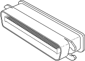
When installing an external SCSI device, you usually find the device in a storage enclosure with both input and output SCSI connectors, so you can use the device in a daisy-chain. If the enclosure is at the end of the SCSI bus, an external terminator module most likely will have to be plugged into the second (outgoing) SCSI port to provide proper termination at that end of the bus (see Figure below).

External terminator modules are available in a variety of connector configurations, including pass-through designs, which are necessary if only one port is available.
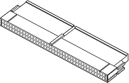
Pass-through terminators also are commonly used in internal installations in which the device does not have built-in terminating resistors. Many hard drives use pass-through terminators for internal installations to save space on the logic-board assembly (see Figure below).

The pass-through models are required when a device is at the end of the bus and only one SCSI connector is available. Other configuration items on a SCSI drive can be set via jumpers. Following are several of the most common additional settings:
-
Start on Command (delayed start)
-
SCSI Parity
-
Terminator Power
-
Synchronous Negotiation
Start on Command (Delayed Start)
If you have multiple drives installed in a system, it is wise to set them up so that not all the drives start to spin immediately when the system is powered on. A hard disk drive can consume three or four times more power during the first few seconds after power-on than during normal operation.
The motor requires this additional power to get the platters spinning quickly. If several drives are drawing all this power at the same time, the power supply can be overloaded, which can cause the system to hang or have intermittent startup problems.
Nearly all SCSI drives provide a way to delay drive spinning so this problem does not occur. When most SCSI host adapters initialize the SCSI bus, they send out a command called Start Unit to each of the ID addresses in succession.
By setting a jumper on the hard disk, you can prevent the disk from spinning until it receives the Start Unit command from the host adapter. Because the host adapter sends this command to all the ID addresses in succession, from the highest priority address (ID 7) to the lowest (ID 0), the higher priority drives can be made to start first, with each lower-priority drive spinning up sequentially.
Because some host adapters do not send the Start Unit command, some drives might simply delay spin-up for a fixed number of seconds rather than wait for a command that never will arrive. If drives are installed in external chassis with separate power supplies, you need not implement the delayed-start function.
This function is best applied to internal drives that must be run from the same power supply that runs the system. For internal installations, I recommend setting Start on Command (delayed start) even if you have only one SCSI drive.
This setting eases the load on the power supply by spinning the drive up after the rest of the system has full power. This method is especially good for portable systems and other systems in which the power supply is limited.
SCSI Parity
SCSI Parity is a limited form of error checking that helps ensure that all data transfers are reliable. Virtually all host adapters support SCSI parity checking, so this option should be enabled on every device. The only reason it exists as an option is that some older host adapters do not work with SCSI parity, so the parity must be turned off.
Terminator Power
The terminators at each end of the SCSI bus require power from at least one device on the bus. In most cases, the host adapter supplies this terminator power; in some cases, however, it does not. For example, parallel port SCSI host adapters typically do not supply terminator power.
It is not a problem if more than one device supplies terminator power because each source is diode-protected. For simplicity's sake, many people often configure all devices to supply terminator power. If no device supplies terminator power, the bus is not terminated correctly and will not function properly.
SCSI Synchronous Negotiation
The SCSI bus can run in two modes: asynchronous (the default) and synchronous. The bus actually switches modes during transfers through a protocol called synchronous negotiation.
Before data is transferred across the SCSI bus, the sending device (called the initiator) and the receiving device (called the target) negotiate how the transfer will take place. If both devices support synchronous transfers, they will discover this fact through the negotiation and the transfer will take place at the faster synchronous rate.
Unfortunately, some older devices do not respond to a request for synchronous transfer and can actually be disabled when such a request is made.
For this reason, both host adapters and devices that support synchronous negotiation often have a jumper that can be used to disable this negotiation so it can work with older devices. By default, all devices today should support synchronous negotiation, and this function should be enabled.