Using Digital Multimeters
One simple test you can perform on a power supply is to check the output voltages. This shows whether a power supply is operating correctly and whether the output voltages are within the correct tolerance range. Note that you must measure all voltages with the power supply connected to a proper load, which usually means testing while the power supply is still installed in the system and connected to the motherboard and peripheral devices.
Selecting a Meter
You need a simple digital multimeter (DMM) or digital volt-ohm meter (DVOM) to perform voltage and resistance checks on electronic circuits. You should use only a DMM instead of the older needle-type multimeters because the older meters work by injecting 9V into the circuit when measuring resistance, which damages most computer circuits.
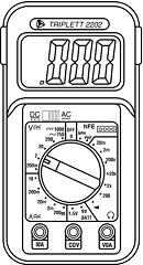
A DMM uses a much smaller voltage (usually 1.5V) when making resistance measurements, which is safe for electronic equipment. You can get a good DMM with many features from several sources. I prefer the small, pocket-size meters for computer work because they are easy to carry around.
Some features to look for in a good DMM are as follows:
-
Pocket size. This is self-explanatory, but small meters are available that have many, if not all, of the features of larger ones. The elaborate features found on some of the larger meters are not really necessary for computer work.
-
Overload protection. If you plug the meter into a voltage or current beyond the meter's capability to measure, the meter protects itself from damage. Cheaper meters lack this protection and can be easily damaged by reading current or voltage values that are too high.
-
Autoranging. The meter automatically selects the proper voltage or resistance range when making measurements. This is preferable to the manual range selection; however, really good meters offer both autoranging capability and a manual range override.
-
Detachable probe leads. The leads easily can be damaged, and sometimes a variety of differently shaped probes are required for different tests. Cheaper meters have the leads permanently attached, which means you can't easily replace them. Look for a meter with detachable leads that plug into the meter.
-
Audible continuity test. Although you can use the ohm scale for testing continuity (0 ohms indicates continuity), a continuity test function causes the meter to produce a beep noise when continuity exists between the meter test leads. By using the sound, you quickly can test cable assemblies and other items for continuity. After you use this feature, you will never want to use the ohms display for this purpose again.
-
Automatic power off. These meters run on batteries, and the batteries can easily be worn down if the meter is accidentally left on. Good meters have an automatic shutoff that turns off the unit when it senses no readings for a predetermined period of time.
-
Automatic display hold. This feature enables you to hold the last stable reading on the display even after the reading is taken. This is especially useful if you are trying to work in a difficult-to-reach area single-handedly.
-
Minimum and maximum trap. This feature enables the meter to trap the lowest and highest readings in memory and hold them for later display, which is especially useful if you have readings that are fluctuating too quickly to see on the display.
Although you can get a basic pocket DMM for as little as $20, one with all these features is priced closer to $100, and some can be much higher. RadioShack carries some nice inexpensive units, and you can purchase the high-end models from electronics supply houses, such as Newark or Digi-Key.
Measuring Voltage
To measure voltages on a system that is operating, you must use a technique called back probing on the connectors. You can't disconnect any of the connectors while the system is running, so you must measure with everything connected. Nearly all the connectors you need to probe have openings in the back where the wires enter the connector.
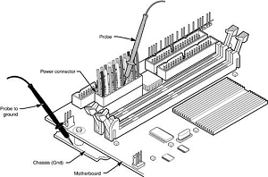
The meter probes are narrow enough to fit into the connector alongside the wire and make contact with the metal terminal inside. The technique is called back probing because you are probing the connector from the back. You must use this back-probing technique to perform virtually all the following measurements.
To test a power supply for proper output, check the voltage at the Power_Good pin (P8-1 on AT, Baby-AT, and LPX supplies; pin 8 on the ATX-type connector) for +3V to +6V of power. If the measurement is not within this range, the system never sees the Power_Good signal and therefore does not start or run properly.
In most cases, the power supply is bad and must be replaced. Continue by measuring the voltage ranges of the pins on the motherboard and drive power connectors. If you are measuring voltages for testing purposes, any reading within 10% of the specified voltage is considered acceptable, although most manufacturers of high-quality power supplies specify a tighter 5% tolerance.
For ATX power supplies, the specification requires that voltages must be within 5% of the rating, except for the 3.3V current, which must be within 4%. Replace the power supply if the voltages you measure are out of these ranges. Again, it is worth noting that any and all power supply tests and measurements must be made with the power supply properly loaded, which usually means it must be installed in a system and the system must be running.

