Network Topologies
Each computer on the network is connected to the other computers with cable (or some other medium). The physical arrangement of the cables connecting computers on a network is called the network topology.
The three types of basic topologies used in computer networks are as follows:
-
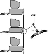
Bus. Connects each computer on a network directly to the next computer in a linear fashion. The network connection starts at the server and ends at the last computer in the network.
-
Star. Connects each computer on the network to a central access point.
-
Ring. Connects each computer to the others in a loop or ring.
These different topologies are often mixed, forming what is called a hybrid network. For example, you can link the hubs of several star networks together with a bus, forming a star-bus network. Rings can be connected in the same way.
Bus Topology
The earliest type of network topology was the bus topology, which uses a single cable to connect all the computers in the network to each other. This network topology was adopted initially because running a single cable past all the computers in the network is easier and less wiring is used than with other topologies.
Because early bus topology networks used bulky coaxial cables, these factors were important advantages. Both 10BASE-5 (thick) and 10BASE-2 (thin) Ethernet networks are based on the bus topology.
However, the advent of cheaper and more compact unshielded twisted-pair cabling, which also supports faster networks, has made the disadvantages of a bus topology apparent. If one computer or cable connection malfunctions, it can cause all the stations beyond it on the bus to lose their network connections.
Thick Ethernet (10BASE-5) networks often fail because the vampire tap connecting the AUI device to the coaxial cable comes loose. In addition, the T-adapters and terminating resistors on a 10BASE-2 Thin Ethernet network can also come loose or be removed by the user, causing all or part of the network to fail.
Another drawback of Thin Ethernet (10BASE-2) networks is that adding a new computer to the network between existing computers might require replacement of the existing network cable between the computers with shorter segments to connect to the new computer's network card and T-adapter.
Ring Topology
Another topology often listed in discussions of this type is a ring, in which each workstation is connected to the next and the last workstation is connected to the first again (essentially a bus topology with the two ends connected). Two major network types use the ring topology:
-
Fiber Distributed Data Interface (FDDI). A network topology used for large, high-speed networks using fiber-optic cables in a physical ring topology
-
Token-Ring. Uses a logical ring topology
A Token-Ring network resembles a 10BASE-T or 10/100 Ethernet network at first glance because both networks use a central connecting device and a physical star topology. Where is the "Ring" in Token-Ring? The ring exists only within the device that connects the computers, which is called a multistation access unit (MSAU) on a Token-Ring network
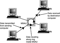 Signals generated from one computer travel to the MSAU, are sent out to the next computer, and then go back to the MSAU again.
The data is then passed to each system in turn until it arrives back at the computer that originated it, where it is removed from the network. Therefore, although the physical wiring topology is a star, the data path is theoretically a ring.
This is called a logical ring. A logical ring that Token-Ring networks use is preferable to a physical ring network topology because it affords a greater degree of fault tolerance. As on a bus network, a cable break anywhere in a physical ring network topology, such as FDDI, affects the entire network.
FDDI networks use two physical rings to provide a backup in case one ring fails. By contrast, on a Token-Ring network, the MSAU can effectively remove a malfunctioning computer from the logical ring, enabling the rest of the network to function normally.
Star Topology
The most popular type of topology in use today has separate cables to connect each computer to a central wiring nexus, often called a hub or concentrator; a switch can also be used in place of a hub.
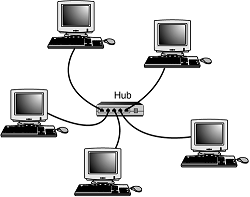 Because each computer uses a separate cable, the failure of a network connection affects only the single machine involved. The other computers can continue to function normally. Bus cabling schemes use less cable than the star but are harder to diagnose or bypass when problems occur.
At this time, Fast Ethernet in a star topology is the most commonly implemented type of LAN; this is the type of network you build with most preconfigured network kits. 10BASE-T Ethernet and 1000BASE-TX Gigabit Ethernet also use the star topology.
10BASE-T can use either Category 3 or Category 5 UTP, whereas Fast Ethernet and Gigabit Ethernet require Category 5 UTP or greater.
Hubs and Switches
As you have seen, modern Ethernet workgroup networks are based on UTP cable with workstations arranged in a star topology. The center of the star uses a multiport connecting device that can be either a hub or a switch. Although hubs and switches can be used to connect the network—and can have several features in common—the differences between them are also significant and are covered in the following sections.
All Ethernet hubs and switches have the following features:
-
Multiple RJ-45 UTP connectors
-
Diagnostic and activity lights
-
A power supply
Ethernet hubs and switches are made in two forms: managed and unmanaged. Managed hubs and switches can be configured, enabled or disabled, or monitored by a network operator and are commonly used on corporate networks. Workgroup and home-office networks use less expensive unmanaged hubs, which simply connect computers on the network.
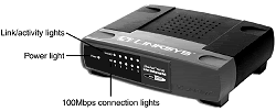 The connection between each workstation and the hub or switch is the UTP cable running from the RJ-45 jack on the rear of the NIC to the RJ-45 jack on the rear of the hub or switch.
Signal lights on the front of the hub or switch indicate which connections are in use by computers; switches also indicate whether a full-duplex connection is in use.
Multispeed hubs and switches also indicate which connection speed is in use on each port. Your hub or switch must have at least one RJ-45 UTP connector for each computer you want to connect to it.
How Hubs Work
A computer on an Ethernet network broadcasts (sends) a request for network information or programs from a specific computer through the cable to the hub, which broadcasts the request to all computers connected to it.
When the destination computer receives the message, it sends the requested information back to the hub, which broadcasts it again to all computers, although only the requesting computer acts on the information. Thus, a hub acts similarly to a radio transmitter and receiver that sends a signal to all radios, but only the radios set for the correct station can send or receive the information.
What the Differences Between Switches and Hubs
Switches are similar to hubs in that they connect computers on a UTP-based Ethernet network to each other and physically resemble hubs. However, instead of broadcasting data to all computers on the network as hubs do, switches use a feature called address storing, which checks the destination for each data packet and sends it directly to the computer it's intended for.
Thus, a switch can be compared to a telephone exchange, making direct connections between the originator of a call and the receiver.
Because switches establish a direct connection between the originating and receiving PC, they also provide the full bandwidth of the network to each port.
Hubs, by contrast, must subdivide the network's bandwidth by the number of active connections on the network, meaning that bandwidth rises and falls depending on network activity.
For example, assume you have a four-station network workgroup using 10/100 NICs and a Fast Ethernet hub. The total bandwidth of the network is 100Mbps. However, if two stations are active, the effective bandwidth available to each station drops to 50Mbps (100Mbps divided by 2). If all four stations are active, the effective bandwidth drops to just 25Mbps (100Mbps divided by 4)!
Add more active users, and the effective bandwidth continues to drop. By replacing the hub with a switch, the effective bandwidth for each station remains 100Mbps because the switch doesn't broadcast data to all stations. Most 10/100 NICs and Fast Ethernet or 10/100 switches also support full-duplex (simultaneous transmit and receive), enabling actual bandwidth to be double the nominal 100Mbps rating: 200Mbps.
Here the differences between the two devices:
| Feature | Hub | Switch |
|---|---|---|
| Bandwidth | Divided by total number of ports in use | Dedicated to each port in use |
| Data Transmission Type | Broadcast to all connected computers | Direct connection between transmitting and receiving computers |
| Duplex Support | Half-duplex only (receive or transmit) | Half- or full-duplex when (receive and transmit) used with full-duplex NICs; full-duplex operation doubles the effective bandwidth of the network |
As you can see, using a switch instead of a hub greatly increases the effective speed of a network, even if all other components remain the same. Because of the improved performance of switches, I recommend them instead of hubs for networks of any size.
Additional Hub and Switch Features
Although older hubs and switches run at only a single speed and have only a few RJ-45 connectors, it makes sense to upgrade to newer, more flexible equipment. Most recent hubs and switches have the following useful features, which are worth asking for:
-
Dual-speed hubs/switches. If you are adding Fast Ethernet (100BASE-TX) clients to an existing 10BASE-T network, you need a dual-speed hub or switch to connect the various types of Ethernet together. Even if you are building a brand-new Fast Ethernet network, a dual-speed hub or switch is useful for occasionally hosting a "guest" PC that has only a standard 10BASE-T Ethernet NIC onboard.
Even though most Fast Ethernet switches and hubs on the market today are actually 10/100 dual-speed models, you might still encounter a Fast Ethernet-only unit. These should be used only on networks that will never have a 10BASE-T connection.
-
Stackable hub or switch with an uplink port. A stackable hub or switch is one that can be connected to another hub, enabling you to add computers to your network without replacing the hub or switch every time it runs out of connections.
Most hubs and switches on the market today are stackable (but very small) hubs, and some older models might lack this feature. You can use this feature to add 10/100 features to an older 10BASE-T-only network and connect a dual-speed hub or switch to the uplink port on your 10BASE-T hub.
-
"Extra" ports beyond your current requirements. If you are connecting four computers together into a small network, you need a four-port hub or switch (the smallest available). But, if you buy a hub or switch with only four ports and want to add another client PC to the network, you must add a second hub or switch or replace the hub or switch with a larger one with more ports.
Instead, plan for the future by buying a hub or switch that can handle your projected network growth over the next year. If you plan to add two workstations, buy at least a six-port hub or switch (the cost per connection drops as you buy hubs with more connections). Even though most hubs and switches are stackable to support the growth of your network, the more ports a hub or switch has, the less expensive per port it will be.
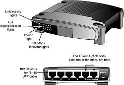
To determine whether a hub or switch is stackable, look for an uplink port, as shown in Figure below. This port looks like an ordinary RJ-45 UTP port, but it is wired differently, enabling you to use a standard-pinout RJ-45 UTP cable to connect it to another hub. Without the uplink port, you'd have to use a specially wired crossover cable.
Typically, hubs and switches with an uplink port allow you to use the port along with all but one of the normal ports on the hub.
For example, one of my associates uses a five-port switch from Linksys that also contains a router (for Internet access) and an uplink port. If his office network expands beyond five computers, he can use the uplink port to add another switch to expand the network and provide the new stations, as well as the original network, with Internet access.
Placement
Although large networks have a wiring closet near the server, the workgroup-size LANs you'll be building don't need a wiring closet. However, the location of the hub or switch is important. Ethernet hubs and switches require electrical power, whether they are small units that use a power "brick" or larger units that have an internal power supply and a standard three-prong AC cord.
In addition to electrical power, consider placing the hub or switch where its signal lights will be easy to view for diagnostic purposes and where its RJ-45 connectors can be reached easily when it's time to add another user or two. In many offices, the hub or switch sits on the corner of the desk, enabling the user to see network problems just by looking at the hub or switch.
If the hub or switch also integrates a router for use with a broadband Internet device, such as a DSL or cable modem, you can place it near the cable or DSL modem or at a distance if the layout of your home or office requires it.
Because the cable or DSL modem usually connects to your computer by the same Category 5 cable used for UTP Ethernet networking, you can run the cable from the cable or DSL modem to the router/switch's WAN port and connect all the computers to the LAN ports on the router/switch.
Except for the 328" (100 meter) limit for all forms of UTP Ethernet (10BASE-T, 100BASE-TX, and 1000BASE-TX), distances between each computer on the network and the hub or switch aren't critical, so put the hub or switch wherever you can supply power and gain easy access.
